Custom Power Electronics Hardware Solutions Taraz Technologies
2.1.1. MPPT Solar Charger and/or Grid-tie inverter. ESS can work with either an MPPT Solar Charger, a grid-tie inverter, or a mix of both. Generally speaking, the MPPT Solar Charger will be more effective than a grid-tie inverter in a small system. This is because an MPPT Solar Charger is up to 99% efficient, whereas the PV energy coming from a.
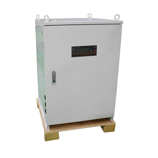
50kW Three Phase Grid Tie Solar Inverter
a single three-phase grid-tie inverter control system from a real and reactive power feeding perspective. Also, a controller was designed in order to minimize power loss during the DC/AC conversion process. These theoretical findings are fundamental to the design of a controller for multiple grid-tie inverters.

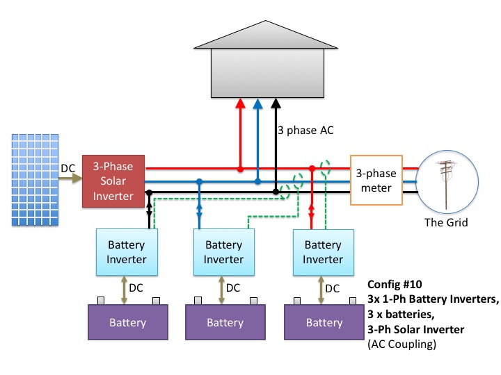
Residential 3Phase GridTie with Battery Backup Product Opinions & Reviews Power Forum
Grid tie inverters work by generating a waveform with the same phase and frequency of the grid but with a magnitude slightly higher so as to drive a forward current. This can all be done using 2 half-bridges and filtering. Each half-bridge is working as a synchronous buck converter with its output voltage after filtering proportional to the PWM.

12000W/12KW grid tie inverter, three phase with 97.5 high efficiency, easy install for
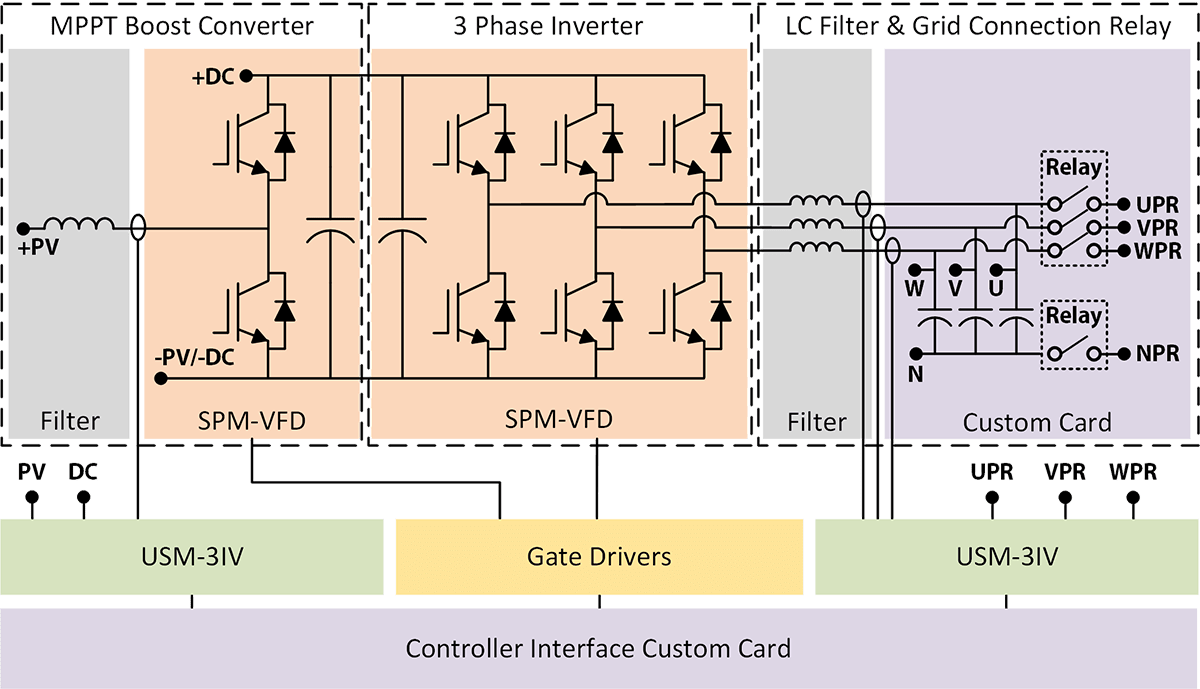
Three-phase inverter reference design for 200-480 VAC drives with opto-emulated input gate drivers 2 System Overview 2.1 Block Diagram Figure 3. TIDA-010025 Block Diagram This reference design is a three-phase inverter drive for controlling AC and Servo motors. It comprises of two boards: a power stage module and a control module.

OmniPower 3 Phase Grid Tie Inverter, 10.2kW to 20.5kW at Rs 11000 in Kannur
The grid-tie inverter ensures that the AC electricity generated by the renewable energy source is synchronized with the grid's AC electricity, making it possible for the electricity to be used directly or sold back to the grid. There are two main types of grid-tie inverters: string inverters and microinverters.

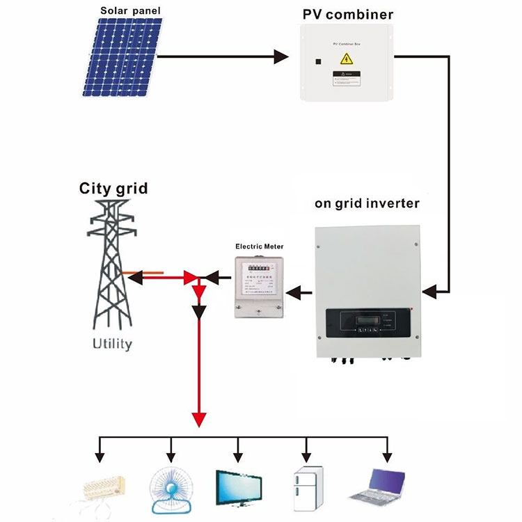
wiring diagram for solar Solar diagram wiring panel rv system 120v installation trailer travel
Back-to-back three-phase converter with grid-tied LCL filter. Three-phase PV inverter for grid-tied applications. AN007. AN011. AN012. Wind turbine generator control using a sensorless algorithm. AN009. This note introduces the control of a three-phase PV inverter with boost converter. The system is meant to connect to the AC grid.

250w 3 phase grid tie inverter,48v ac to 220v ac pure sine power wind inverterin Inverters
Rated nominal/max input voltage at 800V/1,000VDC. Max 10kW/10KVA output power at 400VAC 50/60Hz grid-tie connection. Operating power factor range from 0.7lag to 0.7lead. High voltage (1,200V) SiCMosFET based full bridge inverter for peak efficiency of 99%. Less than 2% output current THD at full load.
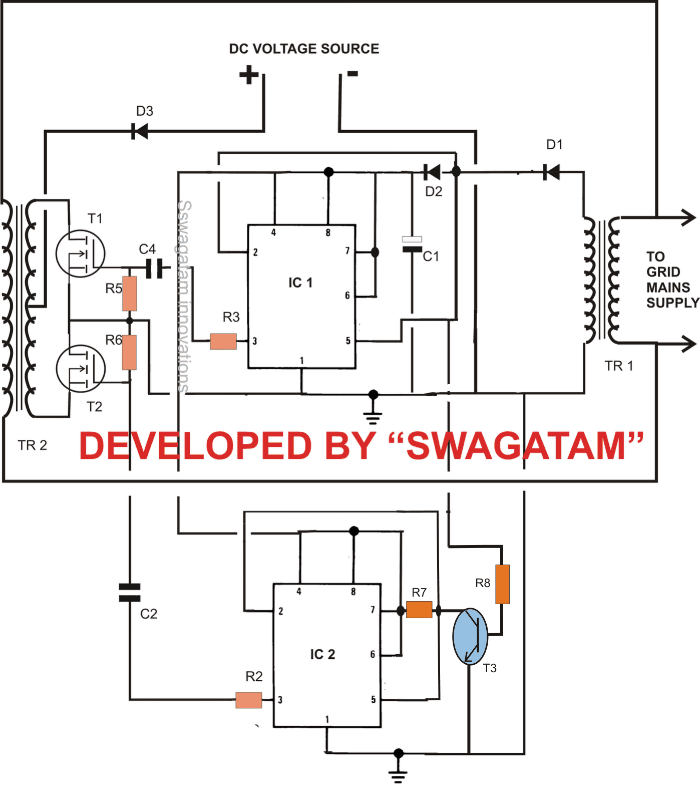
Designing a GridTie Inverter Circuit Homemade Circuit Projects
3-Phase line 60.0HZ 380V 380V 380V 77.5A 77.5A 77.5A Inverter running condition, current generated power, inverterworking 3phaseoutput,systemfrequency Systemvoltage(R/S/T). 3 phase grid tie inverter user manual Author: Inverter.com Created Date: 7/20/2016 4:08:25 PM.
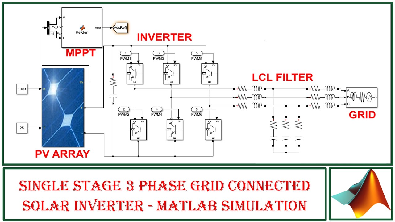
Single stage 3 phase grid connected solar inverter MATLAB Simulation YouTube
Grid-tie inverters are used to convert DC power into AC power for connection to an existing electrical grid and are key components in a microgrid system. This paper discusses the design and.
Wiring Diagram Grid Tie Solar System Wiring Diagram
PV module Inverter Grid There are some differences in the appearance and wiring position of other products in this series. Please refer to the actual product. DC Input PV+: DC+ PV-: DC AC zero line AC fire line L3 phase AC fire line L2 phase AC fire line L1 phase Ground wire port Communication port Contact us: Web: www.inverter.com Tel: +1 800.

Three diagrams with photovoltaics and energy storage Hybrid, Off Grid, GridTied with
A design method for three-phase grid tied inverters is discussed. Four-leg topology is used to cater for unbalance voltage of the grid. A LCL filter is designed to restraint harmonic distortion. Based on three-dimensional space vector control method, voltage feed-forward control strategy is proposed for standalone model of the inverter, and a current wave tracking controller is designed for.

China Customized 3 Phase Grid Tie Inverter Suppliers, Manufacturers Factory Direct Wholesale
Jordan Murray. Grid-tie inverters are used to convert DC power into AC power for connection to an existing electrical grid and are key components in a microgrid system. This paper discusses the.
Grid tie power inverter, On grid solar inverter, Solar energy inverter, Single phase solar inverter
This guide describes three phase inverters only Update of product names Hardware change - new enclosure, interfaces and communication board. Add link to P(Q) diagram application note Maintenance section:. Setting the Inverter to Support 208V 3-wire Grid 44 Connecting the AC Grid to the Safety Switch 45

Three phase grid connected inverter control for PV system A. Phase... Download Scientific Diagram
View the TI TIDA-01606 reference design block diagram, schematic, bill of materials (BOM), description, features and design files and start designing.. bidirectional three-phase three-level (T-type) inverter and PFC reference design TIDM-02002. DC/DC Buck Converter Reference Design TIEVM-HV-1PH-DCAC — Single phase inverter development.
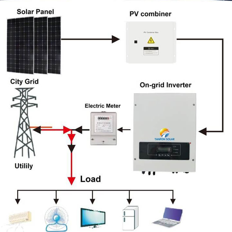
On grid solar inverter, Three phase solar inverter, 100kw solar inverter, Grid tie power
The schematic diagram of the grid-tied three-phase inverter is depicted in Fig. 27.1. The main objective of such a system is to regulate the active power extracted from the PV panel while maintaining the reactive power equal to a specified level [5]. Assuming that the grid is a considered as a receptor, then the voltage equation in the three.

Single‐phase grid‐tie inverter topologies based on tri‐port converters... Download Scientific
The three-phase 400V, 50Hz AC signal output voltage of the inverter, which is fed to the grid, is sampled by a sensor board, which can be observed on the oscilloscope display, as shown in Figure 21.